
What OpenVAT Enables
OpenVAT encodes mesh deformation into textures — storing per-vertex data over time that can be sampled in a shader. This isn’t just baked playback; it’s low-level mesh deformation with real-time control, driven entirely on the GPU.
The export side is simple: vertex data over time, frame by frame. But the power lies in how you use it. In the shader, VATs become a flexible tool for animation, instancing, reactive FX, or even modular motion logic — far beyond just playing back a cached mesh.
Because the data is stored per-vertex, you can drive deformations based on world-space proximity, time offsets, random per-instance values, texture masks, or gameplay triggers. VATs aren’t limited to “just play the animation” — they’re a raw format for sculpting motion at scale.
Common Uses
- Efficient Deformation Playback: Offload complex animation to the GPU for crowd actors, props, or environment detail — with minimal runtime overhead.
- Simulation Bakes: Bring soft body, cloth, dynamic paint, or rigid body simulations into real-time, playable even on performance-constrained platforms.
- Instanced Animation: Use a single VAT to drive hundreds of animated instances, each offset or randomized via material parameters or metadata.
- Morphing & Layered Deformation: Encode blendable shapes (like facial animation, clothing shifts, muscle movement) into per-frame textures.
- Shader-Driven Interactivity: Blend or manipulate VAT playback based on distance fields, world-space logic, masks, or arbitrary gameplay data.
OpenVAT provides the data — what you do with it in the shader is up to you. It’s not a closed animation format. It’s a flexible, engine-ready foundation for real-time deformation.
Limitations
While powerful, OpenVAT is designed for specific data conditions. To maintain accurate encoding and decoding, the following limitations apply:
- Stable Topology Required: Mesh topology must remain constant across all frames. Vertex count, order, and face-corner data must be unchanged—remeshing or dynamic topology invalidates results.
- Mesh-Based Only: OpenVAT currently supports polygonal meshes only. Point clouds, curves, metaballs, and volumetric data are not supported.
- Pre-Baked Motion: Vertex animation is authored offline. Any interactivity must be handled manually via shader logic, such as time remapping or texture blending.
- Format Precision Limits: High-quality playback requires 16-bit or floating-point texture formats. Lower precision (such as 8-bit PNG), although offered as an option, may result in visible artifacts and is not recommended for deformation-critical data.
To circumvent some of these limitations, specifically encoding fluids, point clouds and meshed volumes, I've been developing experimental methods for generative remeshing - which is planned to be released in a future version, when tested and optimized.
Vertex Index Mapping
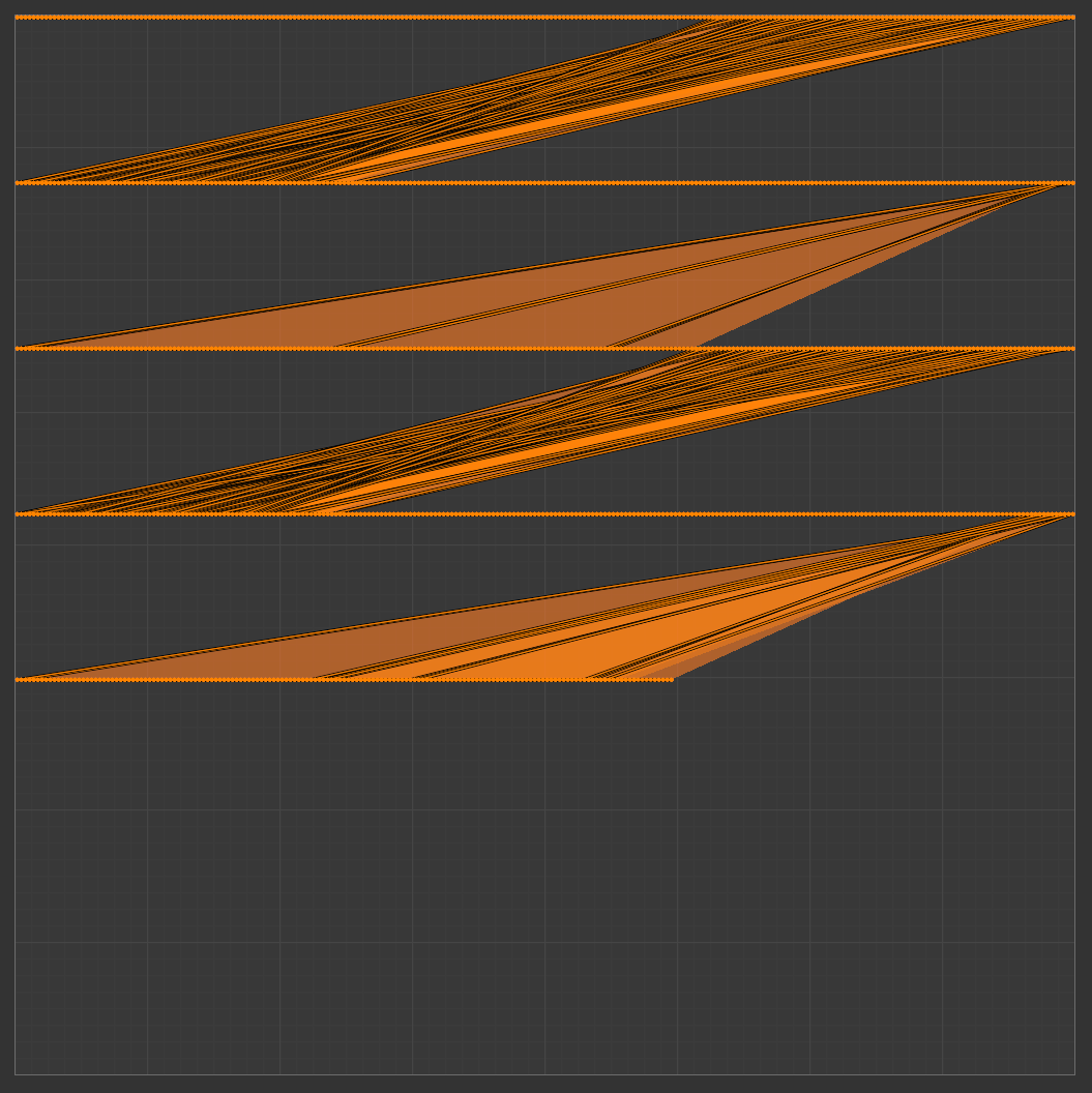
Before the automated encoding process starts, the final height and width of the final VAT need to be determined. This is done using vertex and frame count. I designed OpenVAT to vertically track time (reminicent of old-school vertical tracking DAWs). Each pixel across the X axis will represent a vertex, each pixel down the Y axis will represent 1 frame of time. At this time it is not possible to swap the time/vertex axis - Y is ways frames, X is always vertices.
A second UV Layer is created on the mesh which convents this determined pixel size into UV coordinates, and places each vertex on the center a specific pixel's future location. This UV layer is named VAT_UV and is created in addition to any current existing UV maps (throughout the documentation I may refer to this as UV1, assuming a standard layout on UV0). If your mesh does not have a UV0, preset engine decoders may not work as expected, because they assume a UV index, not string name.
Row Wrapping (default behavior)
Frequently, the number of frames and vertices will be wildly different, with almost all encoding resulting in more vertices than frames. For this reason, a wrapping method is used. Consider a mesh of 800 vertices is animated over 100 frames. With this method, this will result in a 512x512 - where the first 512 vertices are represented on the top row of the texture, and the remaining 288 vertices are 100 pixels lower (starting on pixel 101). This allows for the 100 frames to be read by simply translating each mapped vertex in -Y
Encoding details always is available before you encode except when the target is a collection. It also shows an estimated range of data when using automatic normal-safe edges. This is because it takes more practical computing to determine vertex count when this count is modified by hard edges that will be ripped upon encoding. See edge handling for more about why this happens.
In this method, the texture width w (a power of two) defines the maximum number of vertices that can be packed per row, but the actual number per row is min(w, V) unless the data wraps across multiple rows. When wrapping is needed, the number of rows R is ceil(V / w), and each frame is stacked vertically by R rows. Most rows contain exactly w vertices, except the last, which may be partially filled. Even when w exceeds V, padding may occur, and only a portion of the row holds real data. This ensures power-of-two dimensions while minimizing unused space and maintaining a roughly square layout. This shown calculation assumes the VAT is not packed
OpenVAT Standard engine shaders simply rely on the VAT_UV layer to promote flexibility and ease of understanding. Some engines may reorder vertices on FBX import. Some engines may not allow vertex index sampling via shader. And so, sampling a UV map creates a stable decoding method for many use cases.
$$ \begin{aligned} &\textbf{Inputs:} \\ &\quad V \in \mathbb{N} \quad \text{Number of vertices} \\ &\quad F \in \mathbb{N} \quad \text{Number of frames} \\[8pt] &\textbf{Step 1: Try powers-of-two widths} \\ &\quad \text{For } w \in \{64, 128, \dotsc, 8192\}: \\[2pt] &\quad\quad R = \left\lceil \frac{V}{w} \right\rceil \quad \text{(vertices per row)} \\ &\quad\quad h = \text{next power of 2} \left( F \cdot R \right) \\[8pt] &\textbf{Step 2: Check squareness constraint} \\ &\quad \text{If } |\log_2 w - \log_2 h| > 1: \text{ skip} \\[8pt] &\textbf{Step 3: Choose smallest area (} w \cdot h \text{)} \\[10pt] &\textbf{Result:} \quad (w,\ h,\ R) \end{aligned} $$
Use Single Row Method
Sometimes, it is adventageous to simply map each vertex index in a single row on X. This results in an image which is width of vertex count, height of frame count. The Use Single Row option enforces this encoding method, and does not wrap vertices on Y. This does result in NPOT (non-power-of-two) textures in cases where vertex count and frame count are not exact POT numbers. This is usually safe to use in practice in engines that do not enforce resolution restriction, because uncompressed images do not benefit from POT advantages in mipmapping or compression algorithms.
Since they utilize UV sampling and not index-based image sampling, current engine shader examples are agnostic in decoding either wrapped or single-row encoded VATs.
Sampling Vertex Position as Color
OpenVAT normalizes vertex position attribute values into a 0–1 range per channel based on their temporal min/max distance from deformation basis across the entire animation. This ensures that each attribute fully utilizes the texture's bit depth, maximizing precision while maintaining compatibility with standard texture formats.
When sampling an offset from an established base position
rather than absolute object-sapce vertex positions. In almost all situations, using a proxy-offset method results in cleaner, more finely-sampled range of value that engines handle gracefully as per vertex world position offset (WPO)
To avoid sampling inconsistencies and engine compatibility, HDR range is typically not used in these output textures. If you require full data (not normalized to 0-1) - this is possible in OpenVAT 1.0.4. Set your image export format to EXR32, then an option will appear "Use Absolute Values" - this will encode the full, uncompressed image - including negative values and values greater than 1. Use with caution, only when extremely acurate data is needed and engine compatibility is verified.
Absolute value mode will result in Blender with a VAT which looks incorrect (v1.0.4) - because it still makes an assumption to remap values to range -- this is noted as an issue to resolve in future releases.
To understand color sampling for position, consider following example where a single triange consisting of 3 vertices (v0, v1, v2) over a period of 3 frames (1, 2, 3). For clarity, numbers here have been rounded to a single decimal. in practice, since this information is collected directly from the evaluated depsgraph, we get much higher precision. Note that values in B (Proxy Vertex Position) are constant through time (frames). This is always true in OpenVAT: the deformation proxy acts as static geometry to reference in location to another object.
Like vertex mapping, the following is done automatically by OpenVAT, but understanding the process can help when debugging outputs and creating shaders for use outside of Blender.
| v0 | v1 | v2 | |
|---|---|---|---|
| Frame 1 | (1.0, 1.0, 1.0) | (1.0, 1.0, 1.0) | (1.0, 1.0, 1.0) |
| Frame 2 | (0.0, -1.0, 0.0) | (0.0, -1.0, 0.0) | (0.0, -1.0, 0.0) |
| Frame 3 | (0.0, 0.0, 0.0) | (0.0, 0.0, 0.0) | (0.0, 0.0, 0.0) |
| v0 | v1 | v2 | |
|---|---|---|---|
| Frame 1 | (1.5, 2.0, 3.0) | (2.0, 0.5, 1.0) | (2.5, 1.5, 2.0) |
| Frame 2 | (1.1, -0.2, 1.5) | (1.8, 0.2, -2.0) | (2.0, 0.0, 0.5) |
| Frame 3 | (0.9, 0.0, 0.2) | (1.2, 2.5, 0.8) | (1.0, 1.1, 1.1) |
$$ \mathbf{A} - \mathbf{B} = \begin{bmatrix} (1.5,\ 2.0,\ 3.0) & (2.0,\ 0.5,\ 1.0) & (2.5,\ 1.5,\ 2.0) \\ (1.1,\ -0.2,\ 1.5) & (1.8,\ 0.2,\ -2.0) & (2.0,\ 0.0,\ 0.5) \\ (0.9,\ 0.0,\ 0.2) & (1.2,\ 2.5,\ 0.8) & (1.0,\ 1.1,\ 1.1) \end{bmatrix} - \begin{bmatrix} (1.0,\ 1.0,\ 1.0) & (1.0,\ 1.0,\ 1.0) & (1.0,\ 1.0,\ 1.0) \\ (0.0,\ -1.0,\ 0.0) & (0.0,\ -1.0,\ 0.0) & (0.0,\ -1.0,\ 0.0) \\ (0.0,\ 0.0,\ 0.0) & (0.0,\ 0.0,\ 0.0) & (0.0,\ 0.0,\ 0.0) \end{bmatrix} $$
| v0 | v1 | v2 | |
|---|---|---|---|
| Frame 1 | (0.5, 1.0, 2.0) | (1.0, -1.5, 0.0) | (1.5, 0.5, 1.0) |
| Frame 2 | (1.1, 0.8, 1.5) | (1.8, 1.2, -2.0) | (2.0, 1.0, 0.5) |
| Frame 3 | (0.9, 0.0, 0.2) | (1.2, 2.5, 0.8) | (1.0, 1.1, 1.1) |
$$ \min(x,\ y,\ z) = \left( \min_{i,j} \left( v_{i,j,x} \right),\ \min_{i,j} \left( v_{i,j,y} \right),\ \min_{i,j} \left( v_{i,j,z} \right) \right) = (0.5,\ -1.5,\ -2.0) $$
$$ \max(x,\ y,\ z) = \left( \max_{i,j} \left( v_{i,j,x} \right),\ \max_{i,j} \left( v_{i,j,y} \right),\ \max_{i,j} \left( v_{i,j,z} \right) \right) = (2.0,\ 2.5,\ 2.0) $$
A vector difference is taken (target - proxy) per-vertex per-frame, resulting in a matrix of target geometry's offset from the deformation proxy.
This resulting matrix's per-channel temporal min/max values are found. Note this is established by channel (x,y,z) over all vertices and frames - resulting in 6 found values - X Min, X Max, Y Min, Y Max, Z Min, Z Max.
This resulting matrix is then remapped using these found ranges - (min-max) to (0-1) per channel.
$$ \text{Remap}(v) = \left(\frac{v_x - 0.5}{2.0 - 0.5},\ \frac{v_y - (-1.5)}{2.5 - (-1.5)},\ \frac{v_z - (-2.0)}{2.0 - (-2.0)}\right) \quad \text{Result} = \begin{bmatrix} \left(\frac{0.5 - 0.5}{1.5},\ \frac{1.0 + 1.5}{4.0},\ \frac{2.0 + 2.0}{4.0}\right) & \left(\frac{1.0 - 0.5}{1.5},\ \frac{-1.5 + 1.5}{4.0},\ \frac{0.0 + 2.0}{4.0}\right) & \left(\frac{1.5 - 0.5}{1.5},\ \frac{0.5 + 1.5}{4.0},\ \frac{1.0 + 2.0}{4.0}\right) \\[8pt] \left(\frac{1.1 - 0.5}{1.5},\ \frac{0.8 + 1.5}{4.0},\ \frac{1.5 + 2.0}{4.0}\right) & \left(\frac{1.8 - 0.5}{1.5},\ \frac{1.2 + 1.5}{4.0},\ \frac{-2.0 + 2.0}{4.0}\right) & \left(\frac{2.0 - 0.5}{1.5},\ \frac{1.0 + 1.5}{4.0},\ \frac{0.5 + 2.0}{4.0}\right) \\[8pt] \left(\frac{0.9 - 0.5}{1.5},\ \frac{0.0 + 1.5}{4.0},\ \frac{0.2 + 2.0}{4.0}\right) & \left(\frac{1.2 - 0.5}{1.5},\ \frac{2.5 + 1.5}{4.0},\ \frac{0.8 + 2.0}{4.0}\right) & \left(\frac{1.0 - 0.5}{1.5},\ \frac{1.1 + 1.5}{4.0},\ \frac{1.1 + 2.0}{4.0}\right) \end{bmatrix} $$
| v0 | v1 | v2 | |
|---|---|---|---|
| Frame 1 | (0.00, 0.625, 1.00) | (0.33, 0.00, 0.50) | (0.67, 0.5, 0.75) |
| Frame 2 | (0.40, 0.575, 0.875) | (0.87, 0.675, 0.00) | (1.00, 0.625, 0.625) |
| Frame 3 | (0.27, 0.375, 0.55) | (0.47, 1.00, 0.70) | (0.33, 0.65, 0.775) |
After remapping, values are ready to be defined as floating-point RGB color (0-1) RGB. Min and max values are stored in a sidecar JSON file, so when decoding the VAT in
any shader, we can simply use the reverse of the remapping equation to get the final object-space vertex offset.
$$ \text{Unmap}(v) = \left( x' = x_{\min} + v_x \cdot (x_{\max} - x_{\min}),\ y' = y_{\min} + v_y \cdot (y_{\max} - y_{\min}),\ z' = z_{\min} + v_z \cdot (z_{\max} - z_{\min}) \right) $$
Sampling Vertex Normals as Color
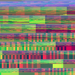
Normals are unit vectors are encoded directly from object space, and so during encoding, we simply remap -1 → 1 into 0 → 1 per channel - and reverse this when decoding in Engine (again, accounting
for potential transformation differences between Blender and the target software).
Why not calculated as an offset like position?
In some cases, it could be adventageous to encode normals as an offset from starting position rather than an absolute object-space vector direction (and may be a future encoding option),
but since the maximum possible range is only (-1 - 1), it decreases
engine-side transformation complexity and reduces compatibility issues to establish encoded normals are to be set as the established object-space normals for the mesh themselves.
RGB-16FLOAT precision is more immediately proven necessicary by analyzing vertex normal encoding:
For VATs using 8-bit formats (e.g. PNG8), this introduces coarse quantization steps of ~1.4°.
16-bit float formats like PNG16FLOAT or RGB16HALF preserve angular precision well below 0.01°, allowing for visually smooth shading and accurate reconstruction.
Handling Edges
VATs inherently sample per-vertex, which causes some complexity when using encoded normals on hard edges. To sample hard edges properly, the VAT needs to encode per-vertex normals for every sharp edge. It is not enough to only separate islands in UV space, because each vertex as it exists in the mesh needs a unique value to sample the seam of a hard edge.
OpenVAT provides a method to automatically perform splitting based on edge data. Edge data is recommended to be reviewed before baking with this option enabled.
Ripping all hard edges can add up in vertex count, be sure to understand the implication of using this feature before enabling it on your mesh. For convenience, the encoding info dropdown displays a range of min-max when this is enabled, as it does not properly count all vertices that are ripped by the operation, but can estimate the maximum (if all edges need to be split).
Edge handling only affects vertex normal encoding; it does not affect positional data.
Transforms
OpenVAT always encodes XYZ > RGB, and assumes content to be exported with Blender's default export orientation of -Z forward, +Y Up. This was done for clarity and consistency of exports - encode once, use in multiple engines - but, requires engine-side transform decoding logic in most cases.
Axis swizzle options are planned as a future improvement, but currently will add a layer of complexity to an already complex topic. It is valid to perform swizzle operations in image manipulation software or custom postprocessing if needed.
Learn more about specific OpenVAT to Engine decoding methods in the engine decoding documentation.
Custom Attribute Sampling
OpenVAT 1.0.4 now allows custom attributes to be encoded to VAT. These values must be per-vertex, float values - usually defined as custom geometry node outputs or via 'store named attribute' node. This allows users to define any animated attribute to be encoded to R, G or B channels (encoding to Alpha is planned but not implemented [v1.0.4]).
A practical example implementation of custom encoding could be absolute world encoding with a pre-defined swizzle for UnrealEngine - here, a user can take Position > (vector math - Multiply by 100) > Separate XYZ > (X channel > Output(name Y), Y channel * -1 > Output(name X), Z > Output(name Z). Set encoding method to "Custom Attributes", scan for attributes, and set R > X, G > Y, B > Z.
Note: Like EXR32 Absolute, the Blender preview of custom attributes will by default affect 'position' of the preview, and will not be accurate, you can modify the geometry node decoding process to simulate your intention for engine decoding or visualize as a color attribute passed to the shader for debugging. (I recommend renaming this geometry node modifier if modifying it so future encoding triggers the an un-modified fresh group to be appended).